Quantcast
Channel: OpenRoads | OpenSite Forum - Recent Threads
Viewing all 19084 articles
Browse latest View live

Re: Cross Section Labeling Error - Geopak Corridor Modeler

$
0
0

You can try a few things to potentially solve this problem.

1.  If you are not using a select series 2 version 08.11.07.536 or higher you may have encountered a defect attributed to having two(2) GPK files in the COGO directory.

2.  The GEOPAKCOM did not register properly on your machine.  So you can go to the BIN folder where you installed the software and as the administrator of your machine you can execute the file 'geopakcom.exe'  This should register the geopakcom and you may be able to run now.

3.  You could also try the following but you do need to have full control set in your user privleges

(1.)     Close all DGN files

(2.)    Bring up the dos prompt and change directory ("cd") to the following location (may be slightly different on your computer):

     cd  C:\Program Files (x86)\Common Files\Bentley Shared\GEOPAK\

(3.)     Key-In "REGSVR32 BentleyControls.ocx" and press Enter.

You should get a message "DllRegistryServer in BentleyControls.ocx succeeded"

(4.)     Now exit the dos prompt, go back into your DGN file and try again

GEOPAK Corridor Modeler Draw Cross Sections from DTM

$
0
0

(Posted on behalf of user)


when drawing surfaces from roadway designer the cross section at the last sta does not draw it only draws the point names is this a tolerance issue?

Re: Saving Multiple RWK Files

$
0
0

Hello Mbachand,

After testing this workflow, it appears that the second opened RWK file will write additional information in the file that will save the file but will also save the information from the other RWK file.

Example:

RWK-A

Original.DTM

Relocation.ALG

Relocation.ITL

RWK-B

Proposed.DTM

Relocation.IRD

When you open RWK-A it will open the Original.DTM, Relocation.ALG, and Relocation.ITL.  You would then open RWK-B and it would open Proposed.DTM and Relocation.IRD.  Upon saving the "Project" using File > Save > Project, it will save the RWK-B file with all the files (ie-Original.DTM, Relocation.ALG, Relocation.ITL, Proposed.DTM, and Relocation.IRD).

Re: GEOPAK Corridor Modeler Draw Cross Sections from DTM

$
0
0

This could very well be a tolerance issue.  You can try cutting a cross section back a few feet along the model and see if the linework appears.  You could also place a key station there where the secion is not drawing or force a template drop at that station.

SS3 - overlay/stripping component problem

$
0
0

hello,

I've noticed strange behaviour of overlay/stripping component when working with Inroads SS3 release. 

Overlay and stripping components are attached to the bottom of my template. Overaly top follows component and its bottom follows surface. Stripping top follows surface and its bottom follows component. The problem is that meshes for both components are created all the time, even if for eg. ovelray is of zero depth and there is only a stripping component on a station range, I have meshes for both o types of components and the overlay mesh follows bottom of my pavement structure as defined in template.

With such kind of behaviour I can not display meshes to differ  stripping and overlays areas.

is anyone playing around with overlay tools here? I would appreciate any tips.

Adam

and what looks like typical in SS3 release, since meshes remain unclosed in 3d model. I can not obtain stripping/overlay components volume via Element Info. Just to append D-123285... with overlay components.

Check Horizontal Integrity ... why me and not you, oh, all mighty software?

$
0
0


Heeelp!

I don't understand the utility of the Check Horizontal Integrity tool.

I have a continuous alignment, but made in a non continuous way (because that a engineer does ... I change my mind, I try to improve my solution).

I can’t move further because I have an “integrity problem”.

There is any way to convince the software to rearrange the elements in the logical way ... and not to waste precious time moving the elements in the Check Horiz... window up and down until I find the exact position?

HEEEELP!

(This smart software I’m talking about is Bentley InRoads/RailTrack V08 1.07)

Existing Ground Cross Sections

$
0
0

Hello,

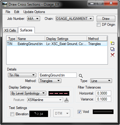
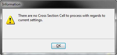
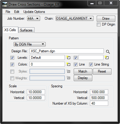
I'm new to GEOPAK.  I am trying to cut existing ground cross sections and keep running into the same error. "There are no Cross Section Cell to process with regards to current settings."

I used the Project Manager dialog box to create all the following objects

I created the existing ground surface by importing point data from an ascii file.

I then created the road centerline chain using the cogo manager.  It's a very simple chain.  Just a straight line from the center of one intersection to the center of another.

Next I created a cross sections patterns drawing and created my pattern lines.

After that I setup the cross sections dialog box as shown below

But I must have missed a step or setting someplace because I always get this dialog box

I am running PowerGEOPAK version 08.11.09.493

On a Dell Precision T3600

Windows 7 Professional 64 bit, 8 GB of Ram.

With Nividia Quadro 600 graphics card.

Any advice would be greatly appreciated.

Thanks

Jason

Re: Existing Ground Cross Sections

$
0
0

Jason,

I am sorry to inform you that this is currently a defect in the version you are running.


Re: Existing Ground Cross Sections

$
0
0

What version would you suggest that I download and install?

Re: Sectioning Strings in Line Mode.

$
0
0

Thank you Andrea for your kind reply. First I apologise for the inconvenience since what I posted last time didn't go well. I used...

SECTION,DESIGN,DESIGN
SECTION,SUBGRADE
019,FE00,4=1
019,WW03,4=1
019,WW02,4=1
019,HE00,4=1
019,GE00,4=1
019,WE06,4=1
019,WC03,4=1
019,GE0I,4=1
019,HE0I,4=1
019,WW0K,4=1
019,WW0L,4=1
019,FE0I,4=1
019,4=-1
173,MC00,3=Z,5=63600,7=-100,8=66520,10=100
999

and the subgrade looks like..

About the product I use MX V 8.5

Addis

Re: Saving Multiple RWK Files

$
0
0

That is interesting behavior and not what I would have anticipated.  Do you think it would be beneficial to control which RWK file is saved?

Re: Sectioning Strings in Line Mode.

$
0
0

Hi Addis

How are you creating the pavement design in MX, is it manually or using the Pavement Design tools?

Vertical Annotation is not annotating the alignment in InRoads SS3

$
0
0

(Posted on behalf of Be Communities User)

InRoads V08.11.09.493

When running View Geometry > Vertical Annotation, the alignment is not displaying the annotation in the profile.

Re: Vertical Annotation is not annotating the alignment in InRoads SS3

$
0
0

Please verify that the geometry was created in the Native product or that the Civil Geometry has been exported to Native product to run this specific command.  If the geometry was created with the Natvie product and you are not seeing the annotation, please verify that all levels are turned on and that the correct profile is selected.

If these items have been verified, please provide me with more information and a dataset to continue troubleshooting this issue.

"A smoothed alignment must be created before using this command" error message with Overlay Tools

$
0
0

(Posted on behalf of Be Communities User)

InRoads V08.11.07.566

I am using the overlay tools in the roadway modeler and after I use the ‘vertical adjustment settings’ command and then ‘process all’ I try to use the ‘smooth adjusted vertical alignment’ command but nothing happens and the ‘apply adjusted vertical alignment’ command returns the following error message.

I have created a corridor named ‘OVERLAY_PROFILE’ and a template named ‘OverlayProfile’ to use overlay tools with.  In the ‘Vertical Overlay Adjustment Settings’ I am entering the following:

In the ‘Vertical Overlay Adjustments Settings’ dialog I click OK and then I click Process All.  After this I open the ‘Smooth Overlay Vertical Alignment’ and enter the settings below and click Apply and nothing appears to happen.  I go on to use the ‘Apply Adjusted Vertical Alignment’ command and that’s when I get the error message.


Re: "A smoothed alignment must be created before using this command" error message with Overlay Tools

$
0
0

It appears that this error message will occur when the smooth alignment cannot be created.  This would occur when the user has Read-Only defined as their access rights.  Please verify that the horizontal alignment is set to Read-Write and re-run the process.

Re: Sectioning Strings in Line Mode.

$
0
0

Hello Mr. Walsh

I created the individual pavement strings in line mode and section them using major option SECTION to creat pavement section strings...but i couldn't creat a single subgrade section string (shown as bold brown line in the picture) using the code i posted.

Addis

Re: Existing Ground Cross Sections

$
0
0

Jason

download and install 08.11.07.615

Re: SS3 area template component quantities / volume

$
0
0

Yes Adam, thanks for pointing that out. However, just to clarify for Juan, said issue would not give bad values/results- it would just make those components non-quantifiable with this method. In his description, he is looking specifically for way to get volumes for "area templates" (which I assume he is referring to surface templates), in which case, while not impossible, I doubt highly that he is clipping these.

I will also add that I used to use Item Browser to set up a report to export to Excel, then grab geometry volumes and copy/paste into my report. But components published in SS3 I have had issues with using Item Browser with...

Long story short, I believe this workflow will suffice his needs to get quick values.

Re: Existing Ground Cross Sections

$
0
0

FYI... we are tracking this problem as D-120640 and D-120337 in our database.  They are scheduled to be fixed in the first update of SS3, post 08.11.09.493 (no schedlue for this update right now, but keep watching for updates).  

Viewing all 19084 articles
Browse latest View live


<script src="https://jsc.adskeeper.com/r/s/rssing.com.1596347.js" async> </script>